In steel fabrication, most costly mistakes don't come from welding or cutting. They come from bad measurements.
Field dimensions taken with tape measures, missing conditions behind walls, uneven concrete, and undocumented site changes can all cause rework, delays, and expensive field fixes. Even small errors can compound when fabricating stairs, railings, embeds, or structural steel.
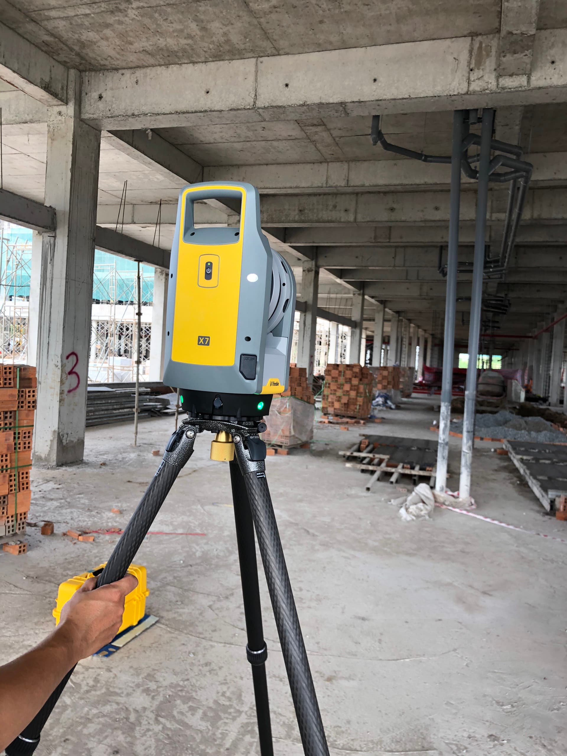
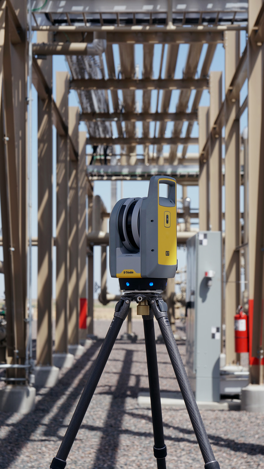
Over the past few years, reality capture using LiDAR scanners has changed how fabrication companies can approach existing conditions. Instead of guessing or relying on incomplete drawings, fabricators can now model directly from highly accurate site data.
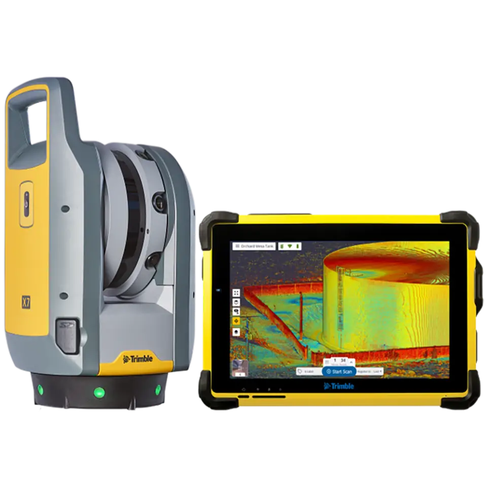
This article explains a practical workflow for using a Trimble LiDAR scanner, importing the data into SketchUp, and detailing fabrication drawings directly from point clouds.
This is not theory. This is a real workflow fabrication shops can implement.
Why LiDAR Scanning Changes Steel Fabrication
Traditional field measuring has limitations:
- You can only measure what you can physically reach
- You cannot easily verify squareness or plumbness
- You cannot capture complex geometry efficiently
- You cannot revisit the site digitally
LiDAR scanning solves these problems by capturing millions of measurement points in minutes.
Instead of individual dimensions, you get a full spatial dataset of the jobsite.
This allows you to:
- Verify existing conditions before fabrication
- Design around real field tolerances
- Reduce change orders
- Prevent installation delays
- Create more accurate shop drawings
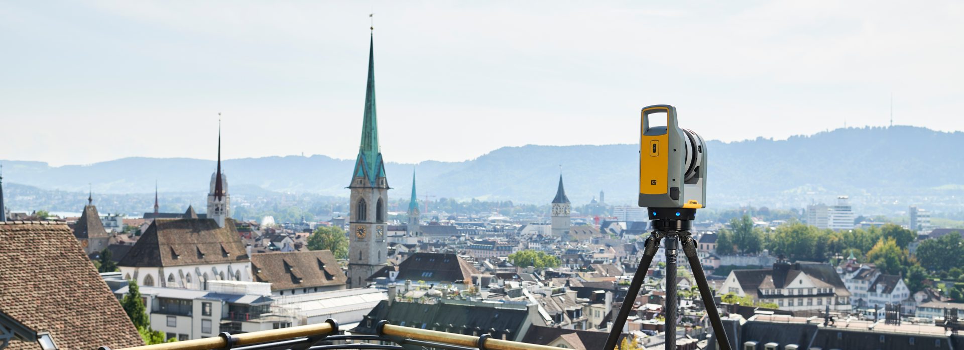
Step 1 – Field Scanning Best Practices (Where Most People Fail)
Most problems with point cloud workflows actually start in the field, not in software.
Bad scans create bad models.
Proper scan planning matters more than scan speed
Before scanning, determine:
- Where steel connects to structure
- Critical connection points
- Areas requiring tight tolerances
- Obstructions that may block line of sight
Think like a fabricator, not a surveyor.
You are not just capturing a building. You are capturing fabrication reference geometry.
Recommended field workflow
- Walk site first without scanning
- Identify key reference surfaces
- Plan scan positions before starting
Typical scan targets
- Column locations
- Concrete edges
- Wall faces
- Anchor bolts
- Stair openings
- Embed plates
- Existing railings
- Structural penetrations
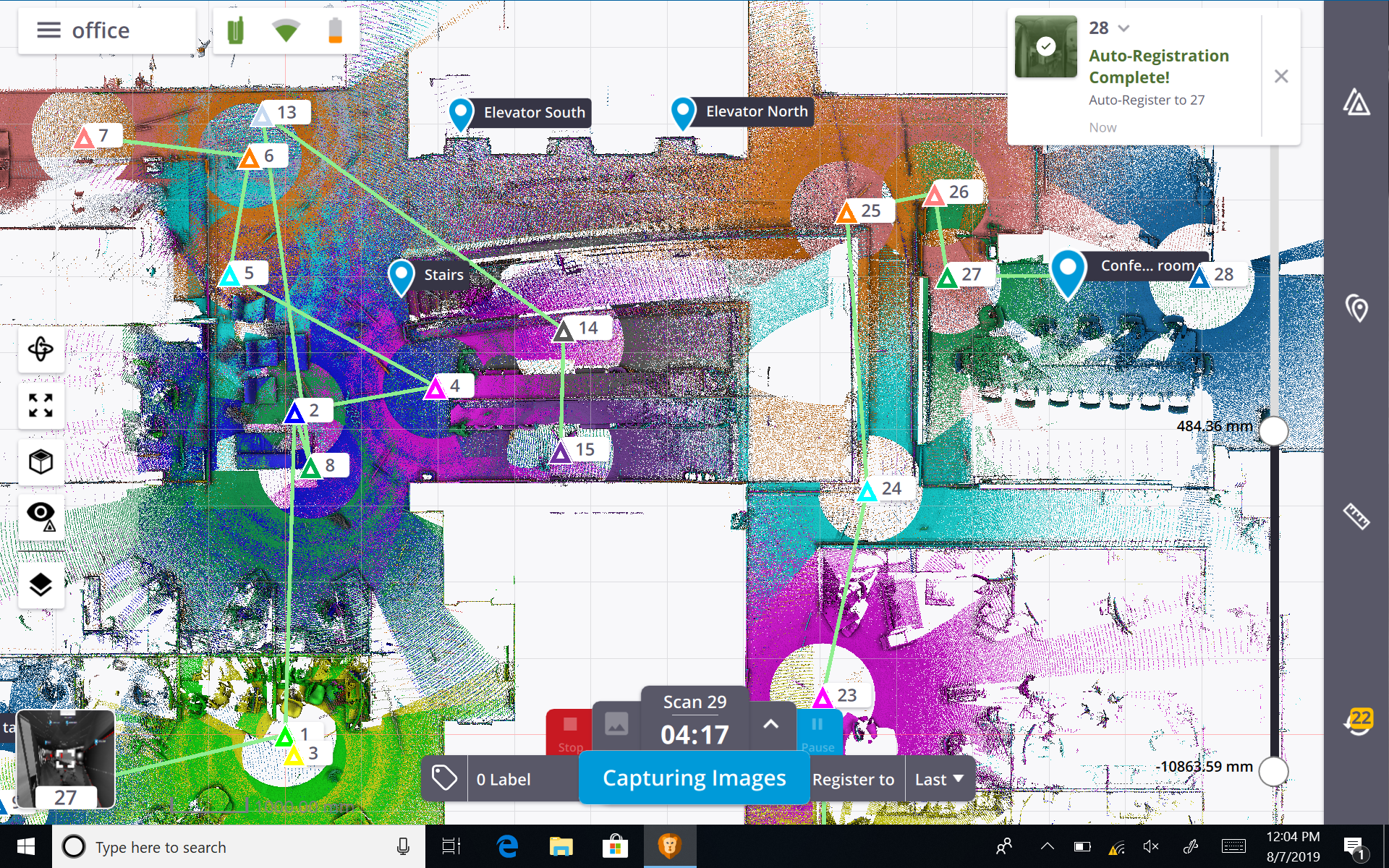
Step 2 – Registration and Cleaning Point Cloud Data
After scanning, the raw data must be registered and cleaned.
Registration aligns multiple scans into one coordinate system.
Using Trimble software, the typical process includes:
- Register scans
- Verify alignment accuracy
- Remove noise
- Trim unnecessary data
- Export usable dataset
What to remove
- People walking through scan
- Moving equipment
- Temporary objects
- Vegetation (if irrelevant)
- Distant geometry not related to project
Reducing unnecessary data dramatically improves SketchUp performance.
Clean data equals faster modeling.
Step 3 – Exporting the Point Cloud for SketchUp
Point clouds typically export as:
- RCP / RCS
- E57
- LAS
- PTS
For SketchUp workflows, common approaches include:
- Using Scan Essentials
- Using Undet plugin
- Using conversion workflows
E57 is often preferred due to compatibility.
Before export
- Verify coordinate orientation
- Confirm units
- Confirm origin location
Bad origin setup causes major modeling headaches later.
Step 4 – Importing Point Clouds into SketchUp
Once imported, performance depends heavily on how you manage the data.
Recommended setup
- Create dedicated point cloud tag
- Lock point cloud layer
- Reduce point display density if needed
Never model directly on an unlocked point cloud. Accidental movement destroys alignment.
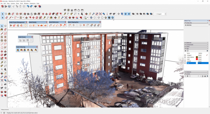
Step 5 – Modeling Steel Directly Over the Point Cloud
This is where the workflow becomes extremely powerful.
Instead of guessing dimensions, you can model directly against real geometry.
Typical workflow
- Establish reference planes
- Trace structural surfaces
- Locate connection points
- Build steel geometry from real conditions
Practical detailing examples
For railings:
- Trace slab edge
- Locate wall deviations
- Model posts exactly where installable
For stairs:
- Verify opening dimensions
- Confirm landing elevations
- Detect slab slope
For embeds:
- Locate concrete face
- Verify anchor locations
- Confirm edge distances
Step 6 – Managing Accuracy Expectations
LiDAR scanning is accurate, but not perfect.
Typical Trimble scanner accuracy is within a few millimeters at close range.
However real accuracy depends on:
- Scan distance
- Registration quality
- Surface reflectivity
- Environmental conditions
Steel fabrication tolerances are often larger than scan tolerances.
This means the scanner is usually more accurate than the fabrication tolerance itself.
Best practice
Use scan data as verification, not absolute truth. Always apply fabrication judgment.
Step 7 – Hardware Considerations Most People Don't Talk About
Point cloud workflows demand more computing power than traditional CAD.
Recommended specs
- 32GB RAM preferred
- Dedicated GPU recommended
- Fast SSD storage
- Modern CPU
Large point clouds can easily exceed several gigabytes.
Without proper hardware, modeling becomes frustrating.
Step 8 – Common Mistakes Fabricators Make When Starting LiDAR Workflows
Most failures come from process mistakes, not technology.
Common mistakes include:
- Taking too few scans
- Not scanning critical areas
- Keeping too much unnecessary data
- Trying to model entire scan at once
- Ignoring coordinate setup
- Modeling from noisy data
The biggest mistake is treating LiDAR like a measuring tool.
It is not. It is a spatial documentation tool.
The real value comes from combining scanning with fabrication expertise.
Real Workflow Example (Video Demonstration)
Before implementing a workflow like this, it helps to see how point clouds function inside SketchUp. The following video shows how scan data becomes usable modeling geometry.
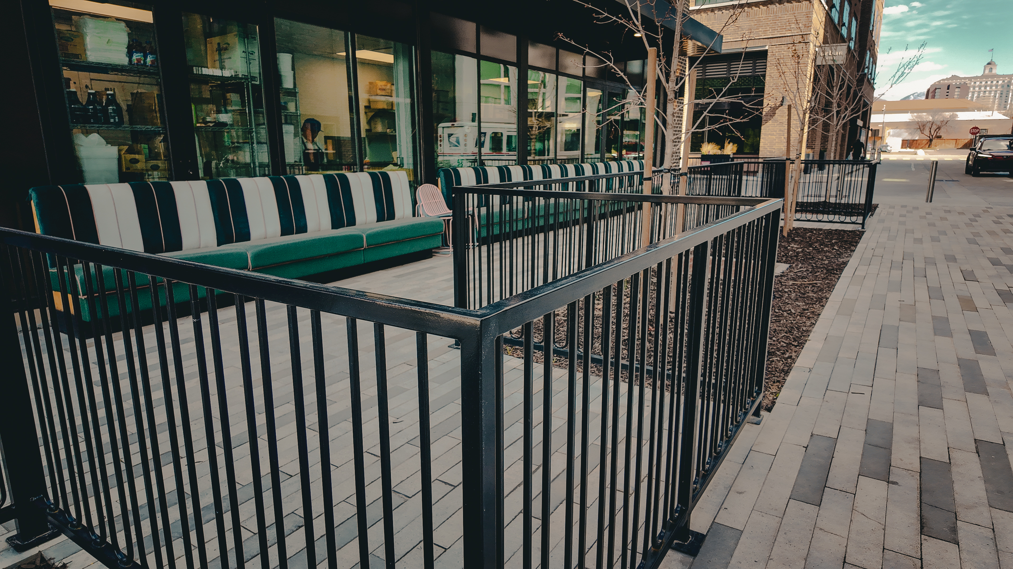
Step 9 – Real Fabrication Use Cases Where This Workflow Excels
LiDAR workflows are especially valuable for:
- Renovations
- Tenant improvements
- Existing building retrofits
- Complex railing layouts
- Custom stairs
- Architectural steel
- Irregular concrete conditions
These are projects where drawings rarely match reality.
Step 10 – Where This Workflow Saves the Most Money
The biggest savings usually come from:
- Prevented remakes
- Fewer site visits
- Reduced install delays
- Better prefab accuracy
- Reduced field welding
A single avoided remake often pays for the scanning time.
For miscellaneous metals contractors, ROI is often immediate.
Final Thoughts
LiDAR scanning is not just a technology upgrade. It is a workflow upgrade.
Fabrication companies that adopt reality capture gain a major advantage because they move from assumption based detailing to data driven detailing.
Instead of asking: Will this fit? You already know.
Instead of discovering problems during installation, you solve them during detailing.
And in fabrication, the earlier a problem is solved, the cheaper it is.
Because in modern fabrication, accuracy is no longer limited by what you can measure. It is limited by what you choose to capture.
Questions about detailing or field verification? Contact us and we can talk through your project.